![[Brads Electronic Projects]](https://bradsprojects.com/wp-content/uploads/2017/06/BPLogo1-240x58.png)
The LED flasher is basically the “Hello World” of microcontroller programming. It is a very good place to get started and even though this is just the beginning, you will still learn a whole heap of instructions.
What you can expect to learn in this tutorial:
- How to connect the pickit 2 to your microcontroller
- How to compile / build your sourcecode
- How to program your microcontroller with the pickit 2
- What each of the 18pins are on the microcontroller
- How to connect an LED to PORTB of the microcontroller
- How to define (create) variables
- Explanation of the bsf instruction
- Explanation of the bcf instruction
- Explanation of the call instruction
- Explanation of the goto instruction
- How to create delays (delay routines)
- How to create loops
- Explanation of the movlw instruction
- Explanation of the movwf instruction
- Explanation of the decfsz instruction
What you will need:
- pic16f628a or pic16f648a microcontroller
- programmer
- electronics breadboard
- 1x LED (any LED will do)
- 1x resistor (any resistor between 150 ohms to 1kohm will do)
- hookup wire
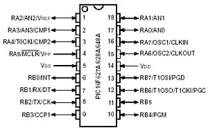
Now is a great time to have a look at the pinout of our microcontroller. The only thing that you really need to be concerned about at this stage is:
- PORTA which is an 8-bit input / output port (RA0 to RA7)
- PORTB which is an 8-bit input / output port (RB0 to RB7)
- VDD which is our +5v power connection
- VSS which is our ground connection
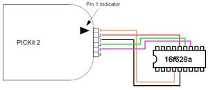
The first thing that we will need to do is connect up the programmer.
- VPP (programming voltage)
- VDD (supply voltage for the pic which is +5v)
- VSS (ground)
- PGD (programming data)
- PGC (programming clock)
- not used (auxilary)
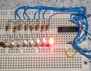
The next thing you need to do is connect up your led and resistor. For this tutorial we will be using PORTB pin 0 (this is leg number 6 on the chip)
Connect one end of the resistor to PORTB pin 0. Connect the other end to a vacant hole not to far from the microcontroller. Then connect the Anode (long leg) of the LED to the resistor, then connect the cathode (short leg) of the LED to a hole just next to the anode. Finally, connect a wire from ground of the microcontroller to the cathode of the LED. and that’s it for the first circuit!
You should have a circuit that looks similar to this.
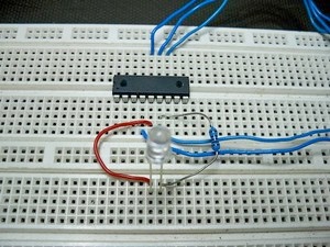
Note: Those blue wires are connected to the PICKIT2
Now that your circuit is all connected, it’s time to get into the coding side of things. Without the code, you will just have a circuit that does basically nothing…
You can download the LED flasher source code at the bottom of this page.
Open up the source code in MPLAB IDE – remember, if you chose to open the asm file in the browser and then copy and paste into MPLAB, then you must first save it as a .asm file! but if you chose to right click the above link, save the file and then open it MPLAB, then it will come up just fine.
So lets have a little bit of a run through of the source code, we will see what has been added from the original template (from tutorial 1) and what it all means. Let’s get into it:
The first thing that has been added is a couple of variables
delay_1 and delay_2
A variable is basically something that we give a name to (practically any name you want really) and MPLAB will then set aside 1byte of ram for our variable. this means that our variable can hold one byte (or 8 bits) of data. In this case, delay_1 and delay_2 will be used in our delay routine. You will hopefully understand variables more as we progress through the tutorials.
The next piece of code that has been added is in between our ‘begin’ label and ‘goto begin’ statment.
bsf PORTB, 0
bsf basically means SET which ever bit i say, at whatever memory location, register or PORT that i say. In this case we are saying SET pin 0 of PORTB to a logic 1. whenever we say set, it means ‘make it a logic 1′ By setting PORTB pin 0, we have effectively turned our LED on, because our LED is connected to PORTB pin 0.
call delay
whenever we say ‘call’ it means stop what your doing for just a moment, jump to whatever label it is that i am calling and do whatever the code says in that label. once we have finished our code in the called label, it will then return to our code, where we left off. In this case, we want to call a delay routine which will make sure that our LED doesn’t turn on and off so fast, so that we can’t see it flashing. So the LED is ON – then we call a delay to keep it on for just a little while (less than a second as you will soon find out) and then once the delay has finished doing what it was doing, it will RETURN to our code here and then continue with the rest of the LED flasher code. (as you will see in the next step – we will turn the LED OFF)
bcf PORTB, 0
bcf basically means CLEAR which ever bit i say, at whatever memory location, register or PORT that i say. In this case we are Clearing pin 0 of PORTB to a logic 0. Whenever we say CLEAR, it means ‘make it a logic 0′ By CLEARING PORTB pin 0 we have effectively turned our LED OFF, because our LED is connected to PORTB pin 0.
call delay
see above for explanation of this (it does exactly the same thing again – but this time holds the LED OFF for a split second)
goto begin
Even though this is in the templae from before, i thought i’d explain it here anyway. whenever we say goto, we basically just want to forget about what we are doing at the present time and just all out – go somewhere else and do that piece of code. We don’t have any intention of trying to return back to this spot and continue on (which is what the call instruction was doing) So that is the difference between using the CALL instruction and the GOTO instruction.
So all of the above is our ‘main program’ or ‘main routine’ this is what runs the show if you like. but you will notice that underneath the main piece of code, we have some other bits of code. I.E. delay. This is called a sub-routine. we call this sub routine from within our main routine. A sub routine just helps us along to get everything running smoothly and more efficiently.
Let’s now look into this delay sub-routine:
movlw d’255′
movlw means ‘move whatever number i tell you (whether it be a hex number, octal, binary or decimal) into the w or working register. In this case we are telling it to move the decimal number (denoted by the letter d) ‘255′. it just so happens that the decimal number 255 is the largest number that we can fit in any one of our variables. This is because the pic 16f648a / 16f628a is an 8-bit microcontroller this means that we can store any binary number from all zeros 00000000 to all ones 11111111 (all zeros in binary 0000000 is equal to zero decimal 0) and (all ones in binary 11111111 is equal to 255 decimal) this means that there are 256 combinations within each 8-bit variable. we could also just have written this movlw b’11111111′ and would have donw exactly the same thing (because binary 11111111 equals decimal 255) or if you like hex numbers you coudl have written this – movlw h’ff’ and it would also have done exactly the same thing. If you’re not exactly sure about number conversions, then some scientific calculators have an inbuilt converter between hex, dec, oct and bin. Or i am sure you could download a free app online to help you also.
In a moment, we will move the number from the w or working register into our delay_1 and delay_2 variables. You may ask “why not just copy 255 straight into delay_1 and delay_2, why bother wasting time first copying it to the w register and then to where we actually want it?” We’ll i’m glad you asked that question. Everytime we want to copy data anywhere, it first has to go through the w register. it’s kind of like the post office. if you want to send a letter to someone, you first have to give it to the post office who then gives the letter to your friend. the post office is like the w register, it is the in-between guy.
movwf delay_1
movwf delay_2
These two lines of code practially do the same thing. movwf means ‘copy whatever is in the w register, into wherever i say’ So in these two cases, the W register contains the decimal number 255 (because we put it in there just before) we are now giving it the instruction to copy this number in to delay_1 and delay_2. So now, delay_1 contains the decimal number 255 and delay_2 also contains 255. From here, we will focus on counting down from 255 to 0. When we reach zero, we will return to our main program.
delay_loop
This is a label. you will soon see that when we have not yet reached zero, we will jump back to this label, this is why we call this delay routine a form of LOOP. because it keeps looping back around or going in circles untill it is complete.
decfsz delay_1, f
This is quite an involved instruction. decfsz basically means ‘decrement (or take 1 away from) the delay_1 variable. store the answer back in delay_1. If the answer is NOT zero, then just continue on with the very next liine BUT if the answer IS zero, then skip the very next line and continue from there.’ It’s quite a big instruction! these are very handy instructions for using in loops. In this case, we are starting from 255, we take 1 away (so the answer is 254) since the answer is NOT zero, then we goto the next line which will tell us to goto the ‘delay_loop’ label. As you can see it will keep looping around, taking 1 away each time untill it finally reaches zero. When it does get to zero, it will skip the next line (which would normally tell us to go to the ‘delay_loop’ label. and it jumps to the next piece of code which is very similar to this piece of code!
An extra note with the above instruction. The ‘f’ at the end of the instruction means that we want the answer stored back in the variable (in this case, the variable is delay_1) we can change the ‘f’ to a ‘w’ if we want and this will store the answer in the w register, rather than in our variable. We will use that function in a later tutorial though.
goto delay_loop
As described above, this will take us back to the ‘delay_loop’ label everytime we come to this line of code. But, we will only come to this line of code as long as the delay_1 variable is not zero.
decfsz delay_2, f
This does basically exactly the same thing as the decfsz delay_1, f except this time we are decrementing the number stored in delay_2. So what happens is delay_1 decrements 255 times, then once that happens, delay_2 decrements once, then it goes back to the delay_loop label and again, delay_1 decrements 255 times, then delay_2 decrements once etc… So what you should be able to see is that we count down from 255 to 0, 255 times! Once we have finished, the next instruction is to return to where we just came from.
Well now that we have the code all explained, it’s time to program it to our microcontroller and see the LED flash! (NOTE: I will only be describing how to program with the PICKIT2 – as this is what I use to program with.)
You should have the Led Flasher source code open in MPLAB. click ‘PROJECT’ then ‘QUICKBUILD’ – MPLAB will then compile (or convert the source code into a hex file that the microcontroller can understand) you should get some green bars flashing and then some BOLD letters saying BUILD SUCCEEDED. Now with your pickit2 plugged in, click ‘PROGRAMMER’ then ‘SELECT PROGRAMMER’ and then click ‘PICKIT2′ if all is well and you have your pickit2 connected correctly you should get a line reading ‘PICkit 2 Ready’ Then all that is left to do is click the program button! which looks like
So now your LED should be flashing, if not then check all your connections. Also you might need to check that you have power going to your microcontroller. Click ‘PROGRAMMER’ and then ‘SET VDD ON’
You can experiment with the code if you like. Here’s some things you might like to try to further your knowledge of delay routines:
Define a third variable named delay_3 (just like we defined delay_1 and delay_2). Once you have done that, modify your delay routine to look like this:
movlw d’255′
movwf delay_1
movwf delay_2
movlw d’02′
movwf delay_3
delay_loop
decfsz delay_1, f
goto delay_loop
decfsz delay_2, f
goto delay_loop
decfsz delay_3, f
goto delay_loop
return
What do you think might happen here? Well all we are doing is adding a third delay loop which allows us to increase the delay time. so this example means that we will count down from 255, 255 times and then do it all again twice! (because delay_3 is set to decimal 2) so you can see that we can increase or decrease our delay to just about what ever we want!
What if you want the LED to stay ON for longer than it is OFF? or the other way around? How could you achieve this?
Well, thats about it for this tutorial. Feel free to write some comments, give me some feedback or ask questions if you run into any trouble.
Until next time, God bless!

Can you explain the PC equ h’02’ line in more detail? I (think I) understand what it does but for this project I don’t understand why it would be needed. Is it a placeholder for if it’s needed in a future project or is its use for this project just non-obvious? Would you use it to jump the interrupt vector if the project were using interrupts? The HEX output for this project is the same with or without the line.
Thanks for the great set of tutorials. God Bless.
Never mind, I figured it out. Thanks again for the tutorials.
Brad
The code file is not downloading.
Without being able to see (all) the code the tutorial is hard to follow.
If you are reducing your server bandwidth cost could you please revise this page to include the code snippet in its entirety (including the config bits)
Thank you
can you please tell me where to add my delay codes to turn off my led for 750ms and on for 1 seconds. I am confused and don’t really know what to do after the following codes that i have. the following code turns on my led for 1 second on and off but that’s not what i need. Can someone please help me?Thank you so much. ;;;;;;; P1 for QwikFlash board ;;;;;;;;;;;;;;;;;;;;;;;;;;;;;;;;;;;;;;;;;;;;;;;; ; ; Use 10 MHz crystal frequency. ; Use Timer0 for ten millisecond looptime. ; Blink “Alive” LED every two and a half seconds. ; Toggle C2… Read more »
Sorry, sir
Can i ask if this things work on PIC 16F84 ??
Thanks in advance..
Hi,
I am new to micro controllers. Iam using PIC16F877A Kit .
I write Assembly language code using MPLab IDE and i get the .HEX file after successful build.
But when i tried to run the HEX file on Kit, its not working.
I tried to upload HEX file using PicPRG software , but when i open the PicPRG software, its getting error, not even open the software, installed software properly, connected PC to PIC16F877 kit using RS232 cable. I tried using PicKit2 burner software , but it failed to detect Kit.
Please help me to solve this problem.
Firstly, your style of PIC tutorials is both refreshing and very easily comprehended by most anyone, and yet each tutorial yields a great deal of pertinent info. Now for a question- I would like to ask you how I would be able to print out each tutorial without losing some of the information. Specifically, your blue lettered “bradsprojects” which appears at the top of each page, interferes with portions of the tutorial data, which does not print. I reside in the United States, and I have Windows 7 Ultimate installed on my computer. Is there something I am failing to… Read more »
How can I make two leds connected to different ports flash twice,after another? I mean alternating with each other.is also possible to add an input to trigger different patterns?
Am a beginner and this looks challenging for me
Awesome! I was able to see the LED stay on longer than it was on.
Thank you for your awesome help and quick replies.
I am now going to move on to the next tutorial, now since I think I understand what’s really going on here 🙂
@Faiyaaz – great to hear that it worked for you 🙂 The d’255′ is the maximum number that you can store in a byte variable. Remember how we had to declare the variables delay_1, delay_2 and delay_3? – they could each hold one byte (or eight bits). When you have eight bits, you can store any number from 00000000 all the way up to 11111111. If you convert these two numbers to decimal you get 0 and 255 respectively. The reason we need these three delay variables is so we can keep the microcontroller busy for a while, before allowing… Read more »
Thanks!! It went great, I see the process was slowed down. Quick question though, d’255′ is that in reference to time? Which snippet of the code actually control the time the led is on/off? I want to keep the LED off for a longer period than it is on and vice versa. I don’t know if I am getting ahead of your tutorials (sorry if I am). Maybe I should just continue to the next tutorial? Lol
Thank you for your help!
I am trying to maximize my knowledge on assembly for micro controllers with your great tutorials!
Hi Faiyaaz, you can make the LED stay on / off for longer just by increasing the number that gets stored in delay_03. i.e. you would change this:
movlw d’02′
movwf delay_3
into something like this:
movlw d’03′
movwf delay_3
or this:
movlw d’04′
movwf delay_3
or this:
movlw d’05′
movwf delay_3
give that a try and let me know how you go!
Hey, so I want to make the LED stay on longer than it is off and vice versa. How do I get around doing that? I failed my HW I know T.T
شاهد اجمل فيديو عن الربح من الانترنت ,
الربح من اليوتيوب , ربح المال
من الانترنت
Thanks for the comments Don and great to hear that the tutorials are going well for you!
What made you want to get started with micro controllers?
This is awsome!!!! i had no clue about anything to do with pic microchips, or programming them. In a matter of hours, i have learned so much. I was ready to give up
when i came across your tutorials. now i am experimenting with my own code. thank you soooooooo nuch !!!!!
Hi Chris, what programmer are you using? It must be different to the PICKIT 2 because the PICKIT 2 interfaces by USB.
Hello, I tried your tutorial on a PIC16F876A Changing just the include and list part of the programm. It seems that after “burn” the programm does not start (at least not when the programmer is connected via RS232 and even if it starts it just stays with the LED on 🙁 I olso tried other tutolials and the result is the same.
Thanx in advance.