![[Brads Electronic Projects]](https://bradsprojects.com/wp-content/uploads/2017/06/BPLogo1-240x58.png)
Welcome to the first instalment of the PIC assembly tutorials.
This set of tutorials is based around the ever popular PIC16F628A and PIC16F648A microcontrollers. We will be programming using assembly language for a number of reasons:
- Assembly is great fun and
- You can gain an excellent understanding of how the microcontroller works due to working with a low level language.
When I first started out in programming microcontrollers, I searched all around the internet finding as much info and tutorials as I could. It was a bit of work finding everything so I thought it would be a great idea to pass on some knowledge through this set of tutorials.
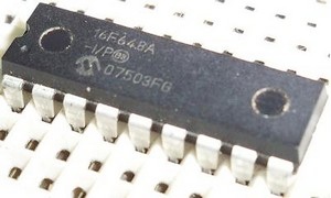
One of the first things you will want to look at is the instruction set. All of the tutorials that you will be learning will utilise the pic16f628a or pic16f648a microcontroller. They are cheap, very common in most electronics stores and have plenty of memory and I/O ports for all the different tutorials that we will be running through.
You can download the datasheet here
When you open it, you want to scroll to page number ‘112′. This page contains a nice printable table telling you what all the instructions are for this microcontroller (and what they do) It’s a good idea to print this out and have it next to you while programming. If you were to scroll down from page 112, you can see that it gives you some more detail on what those instructions do and examples of how to use them – so feel free to have a little bit of a look there also.
You will also need to download yourself a copy of MPLAB IDE – this is a free piece of software that can be downloaded from the microchip website www.microchip.com
As far as hardware goes, you will need to get yourself a microcontroller. Either a 16f628a or 16f648a.
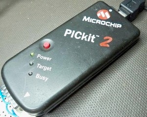
You will also need a programmer (i personally use the pickit2 which costs around $30) The pickit2 is fantastic because you can program your chip while it is still in the circuit. Also you can apply power to your circuit through the pickit2 programmer. So when you are working on a circuit, you click the program button, once it is programmed you click the power button and the circuit will power up!
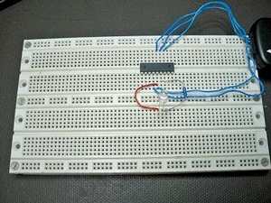
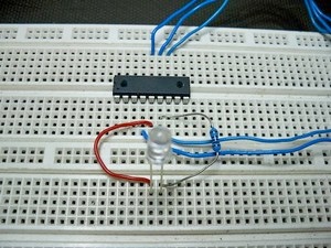
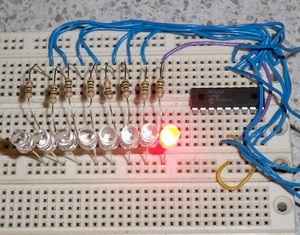
You will need an electronics breadboard and some jumper wires, If you want some very cheap jumper wires, then just purchase a 1metre length of LAN cable, then take all the wires from within the cable, cut them into various short lengths and then you have loads of wires for about $1.
Okay, now that we have had a little introduction, it’s time to get down to business.
Open up MPLAB IDE and wait for it to fully load. Once loaded, click on ‘Project’ then ‘Project Wizard’ You will be presented with a welcome page, click ‘NEXT’ Now you need to select your microcontroller that you will be programming. Just use the drop down box and find either 16f628a or 16f648a (whichever you are using) once selected, click ‘NEXT’ the next page will ask you what toolsuite’s to use, it will automatically be selected to what we want, so just click ‘NEXT’ Now it will ask you to create a new project file. Click ‘BROWSE’ it will now give you a save as box, i recommend making a folder called something like microcontrollers in your my documents folder. open up microcontrollers folder (or whatever you called it and then save the project file as 16f628a or 16f648a (whatever chip you are using) then click ‘NEXT’ Step four will ask you if you want to include any files with your project, You don’t need to worry about this, so just click ’NEXT’
Finally, it will give you a summary page. Click ‘FINISH’ and now you are done setting up MPLAB for our particular microcontroller!
Now, for some strange reason, you now need to quit MPLAB IDE before opening a file (i don’t know why but it has problems if you don’t) so exit out of MPLAB, there’s no need to save the workspace. Open MPLAB IDE again, and we are ready to open our template!
You can download the template that we will be using for all of the tutorials at the bottom of this page.
either right click the link and save the template, or just click on the link to have it open in the browser, and then you can copy and paste the text into MPLA IDE
NOTE: MPLAB IDE will not show up all the various colours and correct formatting untill you save the file as a .asm file you must type in the extension yourself when saving a file in MPLAB IDE for the first time.
At this time you should just have a bit of a look at the template. We will be using this template throughout the tutorials and all we will be doing is adding to it. The template basically gets the microcontroller all set up, ready for our code.
Whenever you see semicolons ; i means that anything after it is just some comments. That means that when building (or compiling your code) MPLAB will ignore the comments. I.E. it is not part of the code, but just a handy way of writing comments to let you know what the code is actually doing.
Well, thats about it for the introduction tutorial.
ok, let’s start with this! thank you!
Very interesting approach to Electronics. Thank you.
Very interesting blog! vivid details. Thank you.
Hi, Brad.
A question, if i may.
Do i have to wear a esd strap when working with an mcu?
Thanks in advance.
Johnny.
First tutorial that begins with a Prayer. I love it.