Page 1 of 1
pull up/down resistors
Posted: Sun Mar 20, 2016 8:17 am
by rd1196
Hello Ive been learning digital logic for a few months now using vhdl and an fpga to do all my school projects and labs. One of the things that confused me at the beginning was that the buttons on the development board acted as active low components rather than the more intuitive '1' when you press the button, I was told by one of the TA's that the switches were active low and that was that. I recently stumbled across the pull up/down resistors subject and understood why the switches were active low, another example of that was the button wiring on brads early circuits like the great race etc..
now that I understand how both work I was wondering why does the pull up resistor seems to be a lot more common than the pull down configuration even if its less intuitive when talking about 1's and 0's
Thanks
Re: pull up/down resistors
Posted: Sun Mar 20, 2016 9:30 am
by Garth
I expect it's because in the days of 74xx TTL and 74LSxx LSTTL logic, it took more current to pull the gates' inputs down. In fact, these inputs are pretty reliably in a high state if not connected to anything at all. Having an adequate pull-down resistor would waste a lot of power, and other gates' outputs would not be strong enough to pull up against it.
TLL was a power hog, and you can imagine how with something like a 74138 3-to-8 decoder or 74154 4-to-16 decoder, where no more than one of eight, or one of 16 outputs is true at a time, it would take more power for the IC to pull the false lines down, against the inputs it is connected to which are trying to pull it up. Letting "false" be the high voltage saved some power and reduced the heating.
With CMOS which came along later, the DC input current is basically zero, being only the femtoamp leakage, whether high or low, so you could pull it up or down passively, either direction, with equal ease. Still, if you have remote switches, there's more likely a ground nearby to connect the other side of the switch to.
In the case of Dallas' 1-Wire interface, you may have a lot of devices interfaced by only a single wire plus ground, and the devices may get the teensy amount of power they need from the passive pull-up resistor at the controller, and store power to keep them operational during those times the line is pulled low for small fractions of a millisecond for signaling. The popular I²C two-wire interface is sometimes run this way too, powering off of the pulled-up lines.
Re: pull up/down resistors
Posted: Sun Mar 20, 2016 7:41 pm
by brad
If I could piggy back on what Garth was saying - I have drawn up a typical TTL NAND gate. There are two diodes, one on each input pin and it is the cathodes that you actually connect in to. So if you have a logic 1 (I.E. 5V) on each input then the diodes are reverse biased and therefore you get basically zero current. It is not until you connect up a logic 0 (I.E. 0V) to an input that you forward bias a diode and therefore actually get some current flow through the diode.
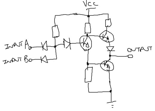
- 225-Resized@1x.png (44.04 KiB) Viewed 11979 times
Re: pull up/down resistors
Posted: Mon Mar 21, 2016 3:38 am
by rd1196
Thanks a lot that was very helpful