Page 2 of 6
Re: help with the screen
Posted: Tue Nov 16, 2010 7:43 am
by rd1196
the part number is: LEDM88OG
and here is the schematic link:
http://www.futurlec.com/Pictures/LEDM88OG_Circuit.gif
Re: help with the screen
Posted: Tue Nov 16, 2010 10:09 am
by brad
That looks exactly the same as my dodgy schematic from my 8x8 LED matrix display's!
If the physical packaging looks just like the one in the images in this forum topic then I'll bet they have the same pinout.
I am yet to see anything different.
Re: help with the screen
Posted: Wed Nov 17, 2010 4:49 am
by bitfogav
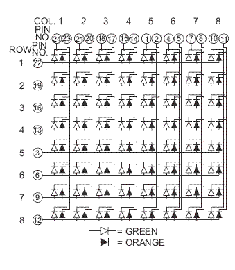
Ive just compared both datasheets of the displays used on this topic (which is what I use) and the one you wanted us to check!
Both looks exactly the same to me

even the pin data and the dimensions are the same, apart from the depth of the screen?!.
Might have to try some of them myself!!

Heres the datasheet of the one I use on this topic:

- redgreen matrix.jpg (87.08 KiB) Viewed 46320 times
And heres the one that you are looking at:

- greenorange matrix.jpg (80.45 KiB) Viewed 46320 times
Re: help with the screen
Posted: Fri Nov 19, 2010 10:09 am
by rd1196
Thanks a lot guys!!
Re: help with the screen
Posted: Tue May 24, 2011 9:44 am
by rd1196
in the schematic says that the vcc and gnd are no shown for the 7442, so does that mean that we dont use theo? and if we do which is the pin for the vcc?
Re: help with the screen
Posted: Tue May 24, 2011 11:20 am
by rd1196
sorry I wrote theo instead of them!!
Re: help with the screen
Posted: Tue May 24, 2011 1:15 pm
by rd1196
Hello brad we build the whole game but then when we were to turn it on I dint work we used a 2 AA battery box it makes up 3 volts total is that enough or do we need more if so how much.
Re: help with the screen
Posted: Tue May 24, 2011 10:11 pm
by brad
You do need to connect vcc and gnd or it won't work
Also, I would put in another 1.5Volt battery to give you 4.5 Volts, that should work just fine
Re: help with the screen
Posted: Tue May 24, 2011 10:38 pm
by rd1196
in the schematic says that the vcc and gnd are no shown for the 7442, so does that mean that we dont use theo? and if we do which is the pin for the vcc?
Re: help with the screen
Posted: Wed May 25, 2011 4:19 am
by bitfogav
rd1196 wrote:in the schematic says that the vcc and gnd are no shown for the 7442, so does that mean that we dont use theo? and if we do which is the pin for the vcc?
Hi rd1196,
If you do a search for the datasheet for a 7442 then it will tell you how to connect it up
but you still need to connect up VCC and GND, So you need to connect GND pin 8 and VCC (power) pin 16.

- SN7442A-pinout.jpg (6.26 KiB) Viewed 46211 times
Re: help with the screen
Posted: Wed May 25, 2011 4:47 am
by rd1196
thanks a lot!!
Re: help with the screen
Posted: Wed May 25, 2011 11:39 am
by rd1196
hello brad for the 10k and 100 ohm resistors what do you recommend 1/4 watt or 1/2 watt?
Re: help with the screen
Posted: Wed May 25, 2011 7:30 pm
by brad
Either is fine, although you don't need one as large as a 1/2 watt
if we have a think about it, the 10k resistor will drop a full 5volts.
5 / 10000 = .5mA
5 * .5mA = 2.5mW
(a 1/4 W resistor = 250mW and a 1/2 W = 500mW)
You can easily use an 1/8 watt resistor (those tiny ones)
Re: help with the screen
Posted: Fri May 27, 2011 9:01 am
by rd1196
in the schematic the 7442 ground is in the 12th pin but in the pic you showed us the its on the 8th pin are they both right or is the schematic wrong.
Re: help with the screen
Posted: Fri May 27, 2011 11:21 am
by rd1196
hey i made this schematic to make it easier for me to read is it good, does it need more, or is some parts wrong. if one thing is wrong can you please tell me so i can fix it and learn more
Thanks
Brad

- The Great Race Schematic.jpg (309.76 KiB) Viewed 46201 times