
As i was making the 8*8 game system i tough of some neat upgrades but i didn't know how to makes them. and i came up to some questions.
1-Can I use a prototype board instead of a bread board.
2-Is it possible to use a 3 color display instead of a 2 color.
-If yes how.
3- Where do i make the PICkit2 plug in on the board.
-And how.
Thank for reading.
-Nicolo86-
8*8 game system modifications
Moderators: Chuckt, Garth, bitfogav
-
brad

- Site Admin

- Posts: 2578
- Joined: Fri Mar 26, 2010 10:30 pm [phpBB Debug] PHP Warning: in file [ROOT]/vendor/twig/twig/lib/Twig/Extension/Core.php on line 1266: count(): Parameter must be an array or an object that implements Countable
Re: 8*8 game system modifications
Yes you can. Breadboard is just very handy for experimenting, but prototype board is perfect for when you have a working circuit.1-Can I use a prototype board instead of a bread board.
Yes, but you would only connect two of the three colours for the 8x8 game system games. My new LEDBOY uses an RGB three colour matrix, which one day I will get around to posting details of.2-Is it possible to use a 3 color display instead of a 2 color.
-If yes how.
There are five connections on the pickit 2 that you will need to connect.3- Where do i make the PICkit2 plug in on the board.
-And how.
1. MCLR
2. VDD
3. VSS
4. PGD (data)
5. PGC (clock)
here's the pinout for the 16f648a or 16f628a
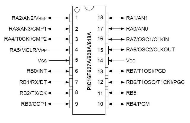
you just need to connect the five pickit 2 connections to the same five connections on the microcontroller.
Last edited by brad on Sat Jul 03, 2010 1:20 pm, edited 2 times in total.
Thanks
Thanks a lot you have been very useful. And one more thing i forgot to ask.
Which batteries should i use and were do i place them
Thanks for all.
-Nicolo86-
Which batteries should i use and were do i place them
Thanks for all.
-Nicolo86-
-
brad
- Site Admin
- Posts: 2578
- Joined: Fri Mar 26, 2010 10:30 pm [phpBB Debug] PHP Warning: in file [ROOT]/vendor/twig/twig/lib/Twig/Extension/Core.php on line 1266: count(): Parameter must be an array or an object that implements Countable
If you wanted to use batteries then there are basically three options.
1. Use a 9Volt battery and a 7805 voltage regulator to regulate the voltage to 5volts.
2. Use four AA batteries and then connect it to the pic through a 1n4001 diode (the diode will prevent you from damaging the pic if you were to connect to batteries around the wrong way and will also reduce the voltage from 6volts to around 5.3volts)
3. Use 3 AA batteries and run the pic at 4.5volts (it will still work just fine like this)
In any case, the positive goes to the VDD pic on the microcontroller and the Negative goes to the VSS pin on the microcontroller
Re: 8*8 game system modifications
Before you said
Thanks
-Nicolo86-
but i can also hook up red and blue or blue and green, or only green and red.Yes, but you would only connect two of the three colors for the 8x8 game system games.
Thanks
-Nicolo86-
-
brad
- Site Admin
- Posts: 2578
- Joined: Fri Mar 26, 2010 10:30 pm [phpBB Debug] PHP Warning: in file [ROOT]/vendor/twig/twig/lib/Twig/Extension/Core.php on line 1266: count(): Parameter must be an array or an object that implements Countable
Good question,nicolo86 wrote:Hey Brad while making the system which i just got all the components i stumbeled on a problem which is:
what are the pins for the RED, GREEN, and COLUMN.
Tanks
-nicolo86-
The pins are arranged like this:
GRAGRAGRAGRA
---------------------
|O O O O O O O O|
|O O O O O O O O|
|O O O O O O O O|
|O O O O O O O O|
|O O O O O O O O|
|O O O O O O O O|
|O O O O O O O O|
|O O O O O O O O|
---------------------
GRAGRAGRAGRA
A = Common Anode
R = Red Cathode
G = Green Cathode
so if you have the LED's facing you (so all pins are underneath), the bottom right pin is common anode 0, then the next pin is red cathode 0, and then green cathode 0.
So all in all, you have eight common anodes for eight rows, then you have eight cathodes of red for eight columns and then eight cathodes of green for eight columns.
One thing to note is that if you rotate the screen around 180 degrees that the pin connections will be out.
So practically the circuit would be like:
G-74373 chip-PIC
R-Resistor-Transistor-Resistor-74373 chip-PIC
A--Resistor-Transistor-Resistor-74373 chip-PIC
G-74373 chip-PIC
R-Resistor-Transistor-Resistor-74373 chip-PIC
A-Resistor-Transistor-Resistor-74373 chip-PIC
G-74373 chip-PIC
R-Resistor-Transistor-Resistor-74373 chip-PIC
A-Resistor-Transistor-Resistor-74373 chip-PIC
And so on. Right?
Thanks
-Nicolo86-
G-74373 chip-PIC
R-Resistor-Transistor-Resistor-74373 chip-PIC
A--Resistor-Transistor-Resistor-74373 chip-PIC
G-74373 chip-PIC
R-Resistor-Transistor-Resistor-74373 chip-PIC
A-Resistor-Transistor-Resistor-74373 chip-PIC
G-74373 chip-PIC
R-Resistor-Transistor-Resistor-74373 chip-PIC
A-Resistor-Transistor-Resistor-74373 chip-PIC
And so on. Right?
Thanks
-Nicolo86-
-
brad
- Site Admin
- Posts: 2578
- Joined: Fri Mar 26, 2010 10:30 pm [phpBB Debug] PHP Warning: in file [ROOT]/vendor/twig/twig/lib/Twig/Extension/Core.php on line 1266: count(): Parameter must be an array or an object that implements Countable
You want to use eight NPN transistors for the common anodes like this:

These eight connections to the base of each transistor is driven by the microcontroller (or a 74373 depending on how you want to do it)
Then the common anodes are again controlled by either the microcontroller or they can connect to their own 74373.
because this is a common anode display, you need a logic 0 to turn on a cathode. the easiest way to do this is to still use logic 1's in your data. but just before you send the data to the cathodes, you invert the data.
e.g. if you wanted to send this data to the LED's
00110110
you would first invert, then send to the LED's like this:
so the data stores the byte of data going to the LED's and the LED's are connected to PORTB. You copy the contents of data into the w register, then you invert all the bits by xor'ing them with all 1's then you send to the LED's.
These eight connections to the base of each transistor is driven by the microcontroller (or a 74373 depending on how you want to do it)
Then the common anodes are again controlled by either the microcontroller or they can connect to their own 74373.
because this is a common anode display, you need a logic 0 to turn on a cathode. the easiest way to do this is to still use logic 1's in your data. but just before you send the data to the cathodes, you invert the data.
e.g. if you wanted to send this data to the LED's
00110110
you would first invert, then send to the LED's like this:
Code: Select all
movf data, w
xorlw b'11111111'
movwf PORTB
- Attachments
-
- common_anodes.PNG (7.22 KiB) Viewed 28169 times
-
brad
- Site Admin
- Posts: 2578
- Joined: Fri Mar 26, 2010 10:30 pm [phpBB Debug] PHP Warning: in file [ROOT]/vendor/twig/twig/lib/Twig/Extension/Core.php on line 1266: count(): Parameter must be an array or an object that implements Countable
You just need to repeat this circuit until you have all eight outputs of both 74373's connected. One of them controls the transistor to provide VCC to the anode. The other one provides a ground to the cathode. (when you place a logic 0 on the 74373 output. If you are using a bi-colour display you just need to add an extra 74373 and connect it to the other colour cathodes (because they are common anode)

- Attachments
-
- 74373 matrix setup.PNG (1.8 KiB) Viewed 28145 times
Now i am rally confused. Sorry but i am not that great with curcuits.
So in your schematics you showed that the red and green cathodes connects to the resistor, then the transistors, again the resistor, and finally the chip. as shown int the schematics, but where i got lost is when you told me that the common cathode gets one resistor and one transistor, and the red and green cathode doesnt gets the 2 resistors and the one transistor.
So exuse my ingnorance, and please can you recap what connects to the different pins.
Tanks for all
-nicolo86-
- Attachments
-
- Immagine.png (180.41 KiB) Viewed 28139 times
Who is online
Users browsing this forum: No registered users and 3 guests