![[Brads Electronic Projects]](https://bradsprojects.com/wp-content/uploads/2017/06/BPLogo1-240x58.png)

I made mention a few weeks ago in the forum that I was working on some VGA experiments. Well, I decided to see if I could get an old Nintendo Gameboy from 1989 working on a VGA monitor. This page documents my experiments and progress in achieving this goal. As I make more progress, I will update this page.
First of all, I would like to give credit where credit is due. I got the idea to do this from Craig over at FlashingLEDs. Craig was able to extract the data going to the Gameboys LCD and then design a microcontroller based circuit that would convert these signals into x and y co-ordinates that allowed him to use an oscilloscope as his screen for the Gameboy.
So having said that, he has done alot of the ground work for me in that his page shows the LCD pinout and also some code to reconstruct the LCD data in a graphics editor called IGOR. I then ported his code over to Visual Basic and this allowed me to reconstruct the gameboy LCD data into an actual image.
Background Info
The Nintendo Gameboy was (believe it or not) made by Nintendo. The Gameboy was released in 1989 and was a huge success despite having quite a hard to see ‘greeny’ LCD screen. It did have excellent battery life and hundreds of fantastic game titles including the ever popular Tetris and Super Mario. Infact I remember when I got a Gameboy for my birthday back in 1991 – I thought I was the coolest kid ever!
These days I still have a Gameboy (in fact numerous Gameboys) and wanted to combine my interest in retro games with my interest in electronics. So here I am working on this project.
Gameboy LCD Connections
Opening up the Gameboy we find the LCD connector.
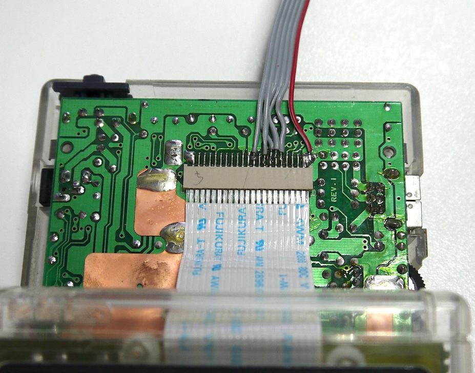
The pins start from number 1 at the left to 21 at the right
The ones we are interested in are:
• Pin 12 – VSync (60Hz)
• Pin 14 – Clock (4Mhz)
• Pin 15 – LCD Data0
• Pin 16 – LCD Data1
• Pin 17 – HSync (9.2Khz)
• Pin 21 – Ground
Grabbing the Data
Thanks again to Craig because he also showed me a great way to extract the LCD data which is to buy myself a Saleae Logic Analyser. These things are so tiny and yet they can grab eight channels of digital data at a time and gives you a great user interface so you can zoom in and out slide through the timeline and get pulse widths etc…So having said that, I connected my logic analyser up to the required pins like this:

Then I was able to grab multiple frames of LCD data. Below is an image showing you one such frame of data.

There is one Vsync pulse (positive edge) to tell the LCD we are starting to draw a frame (from the top left of screen) The 4Mhz clock (negative edge) synchronises the data, the LCD will take note of our two bits of pixel data (on Data0 and Data1) these two bits determine the shade of grey that the pixel will display. Like so:
• 00 = White
• 01 = Light Grey
• 10 = Dark Grey
• 11 = Black
There are 144 individual pixels drawn per line. Once we have drawn the first lot of 144 Pixels, we will get an HSync pulse (positive edge) telling us to go back to the left of screen and down one line. We then draw another 144 Pixels. We do this 160 Times to give a resolution of 160 x 144 Pixels.
Here’s my little Visual Basic program that reconstructs my captured LCD data.

This program accesses my raw LCD data which has been saved to an excel spreadsheet. It mimics the behavior of the Gameboy hardware I.E. it waits for a Vsync pulse, then starts to draw the screen by grabbing data on every clock pulse. It jumps to a new line with every Hysync pulse.
One thing you may be able to see is that the very right hand column of pixels should in-fact be on the very left hand side – I’ll have to fix that!
Update 5th March 2021:
You can download the Visual Basic Project below – however I have no idea where it up to or if it works since I haven’t looked at this project in 8 years!
Gameboy-Screen-Dump.zip (1807 downloads )

Hey Brad,
nice project.
I would like to build something similar. Do you still have the code of your vb app? Can you share it? Should be a nice template to start with.
Thanks!
Hi Brook, I was going to use some sort of microcontroller (most probably a PIC) although I have also been looking a little bit into FPGA’s.
If using a microcontroller, the data from the gameboy would come in by SPI and then would have to either be saved in memory frame by frame or perhaps depending on the differences in timings of the gameboy and VGA, I might be able to do it all pixel by pixel.
One day I would like to get back to this project, I’m just not sure when!
That is a realy exciting project. I would love to make this myself although it’s quite far beyond my current electronics ability. I was wondering what technologies you’d use to make the converter once the data formats are all figured out from using the logic analyzer? Based on your other post maybe with a pic microcontroller? Looking forward to updates on this!